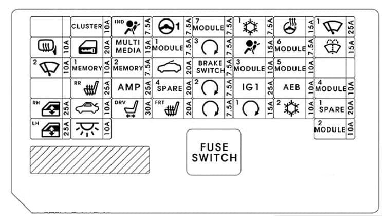
Instrument panel (Driver’s side fuse panel)
| Fuse name | Symbol | A | Protected component |
| SPARE2 | 10 | Spare | |
| CLUSTER | 10 | Instrument Cluster | |
| A/BAG IND | 7,5 | Instrument Cluster, A/C Control Module | |
| MDPS1 | 7,5 | MDPS Unit | |
| MODULE7 | 7,5 | Front Seat Warmer Control Module, Front Air Ventilation, Seat Control Module, Rear Seat Warmer Control Module, Sunroof Motor, Electro Chromic Mirror | |
| A/CON1 |  |
7,5 | E/R Junction Block (RLY.12, RLY. 1B, RLY. 13B), Ionizer, A/C Control Module |
| HTD STRG |  |
15 | BCM |
| WIPER1 | 25 | Wiper Motor, PCM Block (Front Wiper (Low) Relay) | |
| HTD MIRR | 10 | Driver Power Outside Mirror, Passenger Power Outside Mirror, A/C Control Module | |
| DR LOCK |  |
20 | Door Lock Relay, Door Unlock Relay |
| MULTI MEDIA | 15 | DC-DC Converter, Audio A/V&Navigation Head Unit MTH E-Call Module | |
| MODULE1 | 7,5 | Driver/Passenger Smart Key Outside Handle, Driver Door Module, Passenger Door Module | |
| BUTTON START3 | 7,5 | Immobilizer Module, Smart Key Control Module | |
| A/BAG | 15 | SRS Control Module | |
| MODULE6 | 7,5 | Smart Key Control Module, BCM | |
| WASHER | 15 | Multifunction Switch | |
| WIPER2 | 10 | BCM, ECM/PCM | |
| MEMORY1 | 10 | Driver/Passenger Door Module, Driver IMS Module, BCM, Data Link Connector, Digital Clock, Rain Sensor, A/C Control Module, Instrument Cluster, ICM Relay Box (Outside Mirror Folding/Unfolding Relay) | |
| MEMORY2 | 7,5 | — | |
| SUNROOF | 20 | Sunroof Motor | |
| BRAKE SWITCH | 7,5 | Stop Lamp Switch, Smart Key Control Module | |
| MODULE3 | 10 | Stop Lamp Switch, BCM, Sport Mode Switch, Driver Door Module, Passenger Door Module | |
| SPARE3 | 15 | Spare | |
| SPARE5 | 25 | Spare | |
| S/HEATER REAR | 25 | Rear Seat Warmer Control Module | |
| AMP | 25 | DC-DC Converter, AMP | |
| SPARE4 | 20 | Spare | |
| BUTTON START2 | 7,5 | Smart Key Control Module, Immobilizer Module | |
| AEB | AEB | 10 | — |
| MODULE4 | 10 | Parking Assist Buzzer, Blind Spot Detection Radar LH/RH | |
| P/WDW RH | 25 | Power Window RH Relay Driver Safety Power Window Module (RHD) | |
| TRUNK | 10 | Trunk Relay, Trunk Lid Latch | |
| P/SEAT DRV | 30 | Driver Seat Manual Switch, Driver Seat Manual Switch, Driver lms Module | |
| S/HEATER FRONT | 20 | Front Seat Warmer Control Module, Front Air Ventilation Seat Control Module | |
| START | 7,5 | Burglar Alarm Relay, Transmission Range Switch, Ignition Lock & Clutch Switch, Smart Key Control Module, ECM/PCM, E/R Junction Block (RLY.4) | |
| BUTTON START1 | 15 | Smart Key Control Module | |
| A/CON2 | 10 | E/R Junction Block (RLY.12), Blower Motor, B;pwer Resistor, A/C Control Module | |
| SPARE1 | 20 | Spare | |
| P/WDW LH | 25 | Power Window LH Relay Driver Safety Power Window Module (LHD) | |
| INTERIOR LAMP | 10 | Ignition Key ILL. & Door Warning Switch, Trunk Room Lamp, Front Vanity Lamp, LH/RH Room Lamp, Overhead Console Lamp | |
| MODULE2 | 10 | Digital Clock, USB Charging Connector, MTS E-Call Module, Smart Key Control Module, BCM, Audio, A/V & Navigation Head Unit, Power Outside Mirror Switch, DC-DC Converter, AMP, E/R Junction Block (RLY.14) |
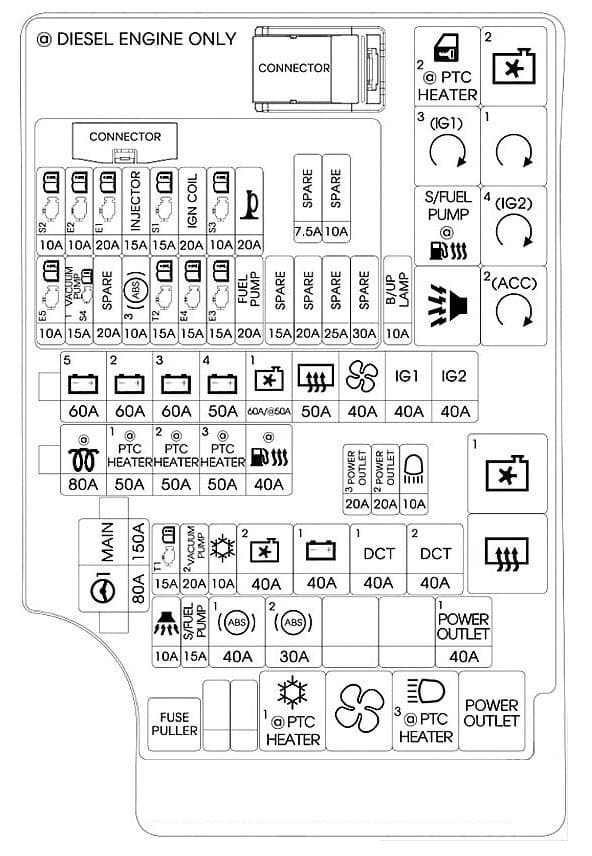
Engine compartment fuse panel
| Fuse name | Symbol | A | Protected component |
| MAIN | 150 | Fuse: F28, F29, F30, F31, F34 | |
| MDPS | 80 | MDPS Unit | |
| BATT5 | 60 | PCB Block (Fuse: F8, F14, F15, F16, Engine Control Relay) | |
| BATT2 | 60 | Smart Junction Block (Fuse: F36, ARISU) | |
| BATT3 | 60 | Smart Junction Block (Fuse: ARISU, IPS) | |
| BATT4 | 50 | Smart Junction Block (Fuse: F20, F26, F27, F33, F34, F35, F41) | |
| COOLING FAN1 | 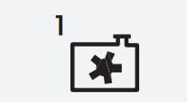 |
50 | RLY.9, RLY.2 (DSL) |
| RR HTD | 50 | RLY.10 | |
| BLOWER | 40 | RLY.12 | |
| IG1 | 40 | Ignition Switch, E/R Junction Block (RLY.3, RLY8) | |
| IG2 | 40 | Ignition Switch, E/R Junction Block (RLY.6) | |
| PTC HEATER1 | 50 | RLY.11B | |
| PTC HEATER2 | 50 | RLY.1B | |
| PTC HEATER3 | 50 | RLY.13B | |
| FUEL HEATER | 40 | RLY.5B | |
| B/UP LAMP | 10 | Electro Chromic Mirror, Rear Combination Lamp (IN) LH/RH, Audio, MTS E-Call Module, Smart Junction Block (IPS Control Module) | |
| POWER OUTLET3 | 20 | Cigarette Lighter | |
| POWER OUTLET2 | 20 | Power Outlet | |
| HEAD LAMP HI | 20 | RLY.13A | |
| TCU1 | 15 | TCM | |
| VACUUM PUMP1 | 20 | — | |
| A/CON | 10 | — | |
| COOLING FAN2 |  |
40 | RLY.9, RLY.2 (GSL) |
| BATT1 | 40 | Smart Junction Block (LEAK CURRENT AUTCUT DEVICE, Fuse: F10, F12, F21, F29, F38) | |
| DCT1 | 40 | TCM | |
| DCT2 | 40 | TCM | |
| B/ALARM HORN | 10 | RLY.7 | |
| ABS1 | 40 | ABS Control Module, ESC Control Module, Multipurpose Check Connector | |
| ABS2 | 30 | ABS Control Module, ESC Control Module, Multipurpose Check Connector | |
| POWER | 40 | RLY.14 |
Engine compartment main fuse panel – PCB (Gamma 1.6 MPI)
| Fuse name | Symbol | A | Protected component |
| SNSR2 | 10 | Purge Control Solenoid Valve, Variable Intake Solenoid Valve, E/R Junction Block (RLY.2, RLY.9) | |
| ECU2 | 15 | — | |
| ECU1 | 10 | ECM/PCM | |
| INJ | 15 | INJECTOR #1-#4 | |
| SNSR1 | 15 | Oxygen Sensor (Up), Oxygen Sensor (Down) | |
| IGN | 15 | Ignition Coil #1-#4, Condenser | |
| SNSR3 | 20 | Fuel Pump Relay, Oil Control Valve #1, Oil Control Valve #2 | |
| HORN | 10 | Horn Relay | |
| ECU5 | 10 | ECM/PCM | |
| SNSR4 | 20 | — | |
| ABS3 | 15 | ABS/ESC Control Module, Multipurpose Check Connector | |
| TCU2 | 15 | Vehicle Speed Sensor, Transmission Range Switch, E/R Junction Block (Fuse: F17) | |
| ECU4 | 20 | ECM/PCM | |
| ECU3 | 10 | ECM/PCM | |
| F/PUMP | 20 | Fuel Pump Relay |
Engine compartment main fuse panel – PCB Block (Nu 2.0 MPI)
| Fuse name | Symbol | A | Protected component |
| SNSR2 | 10 | Purge Control Solenoid Valve, Variable Intake Solenoid Valve, E/R Junction Block (RLY.2, RLY.9) | |
| ECU2 | 15 | PCM | |
| ECU1 | 10 | ||
| INJ | 15 | INJECTOR #1-#4 | |
| SNSR1 | 15 | Oxygen Sensor (Up), Oxygen Sensor (Down) | |
| IGN | 15 | Ignition Coil #1-#4, Condenser | |
| SNSR3 | 20 | Fuel Pump Relay, Oil Control Valve #1, Oil Control Valve #2 | |
| HORN | 10 | Horn Relay | |
| ECU5 | 10 | ECM/PCM | |
| SNSR4 | 20 | — | |
| ABS3 | 15 | ABS/ESC Control Module, Multipurpose Check Connector | |
| TCU2 | 15 | Vehicle Speed Sensor, Transmission Range Switch, E/R Junction Block (Fuse: F17) | |
| ECU4 | 20 | PCM | |
| ECU3 | 10 | PCM | |
| F/PUMP | 20 | Fuel Pump Relay |
Engine compartment main fuse panel – PCB Block (UII 1.6 TCI)
| Fuse name | Symbol | A | Protected component |
| SNSR2 | 10 | Purge Control Solenoid Valve, Variable Intake Solenoid Valve, E/R Junction Block (RLY.2, RLY.9) | |
| ECU2 | 15 | — | |
| ECU1 | 10 | ECM | |
| INJ | 15 | ||
| SNSR1 | 15 | Lambda Sensor #1, Lambda Sensor #2 | |
| IGN | 15 | — | |
| SNSR3 | 20 | Fuel Pump Relay, Air Flow Sensor, Camshaft Position Sensor, Oil Control Valve | |
| HORN | 10 | Horn Relay | |
| ECU5 | 10 | ECM | |
| SNSR4 | 20 | Fuel Filter Warning Sensor, Glow Relay Unit | |
| ABS3 | 15 | ABS/ESC Control Module, Multipurpose Check Connector | |
| TCU2 | 15 | TCM, Transmission Range Switch | |
| ECU4 | 20 | — | |
| ECU3 | 10 | PCM | |
| F/PUMP | 20 | Fuel Pump Relay |
Assignment of the relay
| Symbol | Relay NO. | Protected component | Type |
| RLY.1B | PTC HEATER #2 Relay | MICRO | |
 |
RLY.2 | COOLING FAN2 Relay | MICRO |
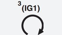 |
RLY.3 | PDM #3 (IG1) Relay | MICRO |
| RLY.4 | START #1 Relay | MICRO | |
| RLY.5A | SUB FUEL PUMP Relay | MICRO | |
| RLY.5B | FUEL HEATER Relay (D4FB) | MICRO | |
 |
RLY.6 | PDM #4 (IG2) Relay | MICRO |
| RLY.7 | B/ALARM HORN Relay | MICRO | |
| RLY.8 | PDM #2 (ACC) Relay | MICRO | |
 |
RLY.9 | COOLING FAN1 Relay | MINI |
| RLY.10 | REAR HEATED Relay | MINI | |
| RLY.11 | A/C Relay | MICRO | |
| RLY.11B | PTC HEATER #1 Realy (D4FB) | MICRO | |
| RLY.12 | BLOWER Relay | MICRO | |
| RLY.13A | H/LAMP HI Relay | MICRO | |
| RLY.13B | PTC HEATER #3 Relay (D4FB) | MICRO | |
| RLY.14 | POWER OUTLET Relay (D4FB) | MICRO |
WARNING: Terminal and harness assignments for individual connectors will vary depending on vehicle equipment level, model, and market.
