Engine compartment fuse box
The Front Distribution Unit is located on the right side of the engine compartment, next to the battery.
| No. |
A |
Function/component |
| F01 | 60 | Body Controller |
| F02 | 40 | Front Heated Seats, Second 12 Volt IP Outlet |
| 60 | Rear Power Window Including Front Heated Seats, Second 12 Volt IP Outlet | |
| F03 | 20 | Ignition Switch |
| F04 | 40 | BSM System Module |
| F06 | 30 | Radiator Fan – Low Speed |
| F07 | 40 | Radiator Fan – High Speed |
| F08 | 40 | Blower Motor |
| F10 | 10 | Horn |
| F11 | 10 | Secondary Loads ECM |
| F14 | 15 | High Beam |
| F16 | 5 | ECM and Transmission Shifter |
| F17 | 25 | ECM Power Loads |
| F18 | 5 | ECM Load, Main Relay |
| F19 | 7.5 | Air Conditioning |
| F20 | 30 | Rear Defroster |
| F21 | 5 | Key Unlock |
| F22 | 10 | Primary ECM Loads |
| F23 | 20 | BSM System |
| F24 | 5 | BSM System, Positive Key and Steering Angle Sensor |
| F30 | 15 | Fog Lamp |
| F83 | 20 | Fuel Pump |
| F84 | 15 | AT Module |
| F85 | 20 | Rear Power Outlet 12V |
| F86 | 30 | IP Power Outlet 12V |
| F87 | 5 | IBS |
| F88 | 7.5 | External Mirror Defrost |
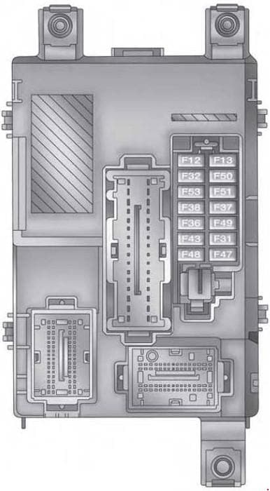
The instrument panel fuse panel
The interior fuse panel is part of the Body Control Module (BCM) and is located on the driver’s side under the instrument panel.
| No. |
A |
Function/component |
| F53 | 5 | KL 30 (+30) – IPC |
| F38 | 20 | Central Doors Locking |
| F36 | 10 | KL 30 (+30) – TPMS, EOBD, HVAC, Radio |
| F43 | 15 | Bi-Directional Washer Pump |
| F48 | 20 | Passenger Power Windows |
| F50 | 7.5 | KL 15 (+15) – Air-Bag |
| F51 | 7.5 | KL 15 (+15) – External Mirror Adjustment Command, HVAC, RVC, HWB Coils |
| F37 | 5 | KL 15 (+15) – Brake Pedal Switch (N.O.), IPC, Brake Pedal Switch (N.C.) |
| F49 | 5 | KL 15 (+15) – PAM, CSS Lighting, ECM Backlighting, TIM |
| F31 | 5 | KL 15a (INT A) – HWB, MCO |
| F47 | 20 | Driver Power Windows |
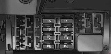
Central Unit Fuse Panel
The interior fuse panel is part of the Body Control Module (BCM) and is located on the driver’s side under the instrument panel.
| No. |
A |
Function/component |
| F1 | 10 | Front Heated Seat Driver |
| F2 | 10 | Front Heated Seat Passenger |
| F3 | 20 | Rear Power Window Driver side |
| F4 | 20 | Rear Power Window Passenger side |
| F5 | 15 | 2nd Instrument Panel Power Outlet 12V |
WARNING: Terminal and harness assignments for individual connectors will vary depending on vehicle equipment level, model, and market.

