Underhood Fuses
The Front Power Distribution Center is located on the driver’s side of the engine compartment.
| Cavity | Maxi fuse | Mini fuse | Description |
| F01 | 40 | ESC Pump | |
| F02 | 20 (3.6 Gasoline Engine) | Starter Relay 3.6L (3.6 Gasoline Engine) | |
| 50 (3.0 Diesel Engine) |
Glow Plug Unit (3.0 Diesel Engine) | ||
| F04 | 50 (3.6 Gasoline Engine) | Secondary PDC (Trans Power Relay, Vacuum Pump, KL30 for STM) (3.6 Gasoline Engine) | |
| 40 (3.0 Diesel Engine) | Fuel Filter Heater (3.0 Diesel Engine) | ||
| F05 | 30 | SELESPEED Pump RELE (3.0 Diesel Engine) – If Equipped | |
| F06 | 40 (non A/C) | Engine Cooling Fan – 2nd Speed | |
| 60 (A/C) | |||
| F07 | 50 (non A/C) | Engine Cooling Fan – 1st Speed | |
| 60 (A/C) | |||
| F08 | 40 | Passenger Compartment Blower | |
| F09 | 15 | Rear Power Outlet | |
| F10 | 15 | Horn | |
| F11 | 15 | MPROP-DRV (3.0 Diesel Engine) — If Equipped | |
| F14 | 20 | Power Outlet | |
| F15 | 7,5 | USB Charger | |
| F16 | 7,5 | KL15 STM (3.6), KL15 Starter Relay Coil (3.6 Gasoline Engine) KL15 MTA, KL15 Shift Lever Unit, KL15 ECM, KL15 Starter Relay Coil (3.0 Diesel Engine) | |
| F17 | 20 | ECM, Injectors (3.6 Gasoline Engine) | |
| Secondary Loads, ECM (3.0 Diesel Engine) | |||
| F18 | 7,5 | KL30 ECM, KL30 Main Relay Coil (3.6 Gasoline Engine) | |
| 7,5 | KL30 MTA, KL30 ECM, KL30 Main Relay Coil (3.0 Diesel Engine) | ||
| F19 | 7,5 | A/C Compressor (If Equipped) | |
| F20 | 30 | Windshield Wiper | |
| F21 | 15 | Fuel Pump | |
| F22 | 20 | ECM, Ignition Coils (3.6 Gasoline Engine) | |
| 20 | ECM, Primary Loads (3.0 Diesel Engine) | ||
| F23 | 20 | ESC Valves | |
| F24 | 7,5 | KL15 Vacuum pump relay coil (3.6 Gasoline Engine) — If Equipped | |
| F30 | 15 | Heated Mirrors |
Front PDC Additional Fuses
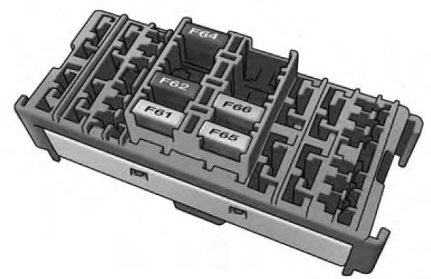
The additional fuse box is located inside the front PDC Box.
| Cavity | Mini fuse | Description |
| F61 | 20 | Vacuum Pump (3.6 Gasoline Engine) — If Equipped |
| F62 | 30 | Transmission Power RELE (3.6 Gasoline Engine) — If Equipped |
| F64 | 7,5 | Urea Pump (3.0 Diesel Engine) — If Equipped |
| F65 | 25 | Urea NOX Sensor 1–2 — PM Sensor (3.0 Diesel Engine) — If Equipped |
| F66 | 5 | STM (3.6 Gasoline Engine) — If Equipped |
Interior Fuses
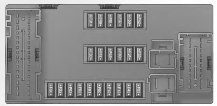
The interior fuse panel is part of the Body Control Module (BCM) and is located on the driver’s side under the instrument panel.
| Cavity | Mini fuse | Description |
| F12 | 10 | Right Low Beam |
| F13 | 10 | Left Low Beam |
| F31 | 5 | INT/A |
| F32 | 10 | SBMT |
| F34 | 7,5 | Clearance Lights |
| F36 | 15 | +30 (ACM – TPCU – RRM – DLC) |
| F37 | 5 | INT (BRAKE NO – IPC) |
| F38 | 15 | Central Locking |
| F42 | 5 | INT (BSM – SAS – BRAKE NC) |
| F43 | 20 | Bi-Directional Washer Pump |
| F47 | 20 | Driver Power Window |
| F48 | 20 | Passenger Power Window |
| F49 | 5 | INT (PAM – CCS – RRM – ECM) |
| F50 | 7,5 | INT (ORC) |
| F51 | 5 | INT (REAR CAMERAAUX) |
| F53 | 5 | +30 (IPC) |
| F90 | 7,5 | Left High Beam |
| F91 | 7,5 | Right High Beam |
| F92 | 7,5 | Left Fog Lamp |
| F93 | 7,5 | Right Fog Lamp |
Right Central Pillar Fuses
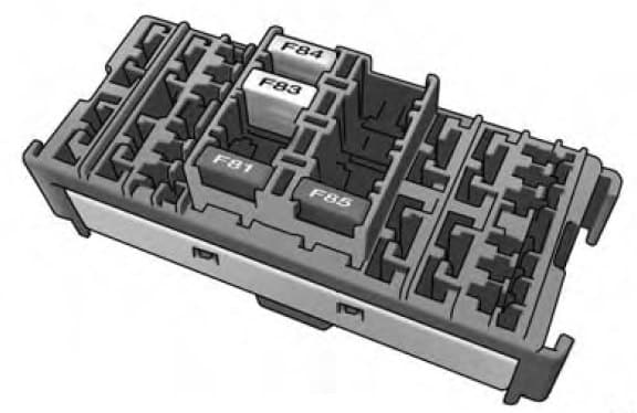
The right central pillar fuse panel is located on the interior side at the base of the passenger side B pillar.
| Cavity | Mini fuse | Description |
| F81 | 7,5 | Seat Heater |
| F83 | 20 | Rear Left Windows Heater |
| F84 | 20 | Rear Right Windows Heater |
| F85 | 10 | Rear Heater Prep |
WARNING: Terminal and harness assignments for individual connectors will vary depending on vehicle equipment level, model, and market.


