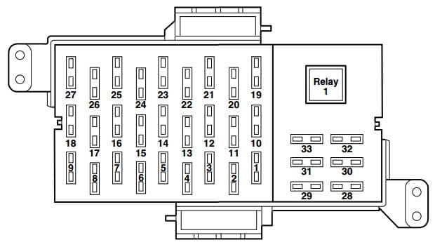
Passenger compartment fuse panel
The fuse panel is located below and to the left of the steering wheel by the brake pedal. Remove the panel cover to access the fuses.
| Fuse/relay | Ampere rating [A] | Description |
| 1 | 15 | Cluster, Lighting Control Module (Interior Lighting) |
| 2 | 10 | Ignition (ON) – Electronic Automatic Temperature Control (EATC) module, A/C mode switch (vehicles equipped with manual A/C only), A/C blower relay coil |
| 3 | 10 | EATC module |
| 4 | 10 | Ignition (ON) – Anti-lock Brake System (ABS) module, Rear Air Suspension Module (RASM), Variable Assist Power Steering (VAPS) |
| 5 | 10 | Speed control deactivation switch, Stop signal |
| 6 | 10 | Ignition (ON) – Cluster |
| 7 | 15 | LCM (Park lamps, Corner lamps) |
| 8 | 10 | LCM |
| 9 | 10 | LCM (Switch illumination) |
| 10 | 5 | Ignition (START) – Audio mute |
| 11 | 10 | Ignition (ON/ACC) – window relay coil |
| 12 | 10 | Ignition (START) – Starter relay coil, DTRS |
| 13 | 10 | Ignition (ON/ACC) – Wiper module |
| 14 | 10 | Ignition (ON) – BTSI (Floor-shift transmission) |
| 15 | 7,5 | Ignition (ON/ACC) – LCM, Door lock switch illumination, Heated seat switch illumination, Moonroof, Overhead console, Electrochromatic mirror |
| 16 | 15 | Ignition (ON) – Turn signals |
| 17 | 10 | Ignition (ON/ACC) – Audio |
| 18 | 10 | Ignition (ON) – A/C mode switch (vehicles equipped with manual A/C), Blend door, Heated seat modules |
| 19 | 10 | LCM (Left-hand low beam) |
| 20 | 10 | Ignition (ON/START) – Back-up lamps |
| 21 | 10 | LCM (Right-hand low beam) |
| 22 | 10 | Ignition (ON/START) – Restraint Control Module (RCM), Occupant Classification Sensor (OCS), Passenger Air bag Deactivation Indicator (PADI) |
| 23 | 15 | Multi-function switch (Flash-to-pass), LCM (High beams) |
| 24 | 10 | Ignition (ON/START) – Passive Anti-Theft System (PATS) module, Powertrain Control Module (PCM) relay coil, Fuel relay coil, Ignition coil relay coil |
| 25 | 10 | Autolamp/Sunload sensor, Power mirrors, Door lock switches, Mirror switch, Keypad switch, Decklid switch, Adjustable pedal switch, DDM |
| 26 | 10 | Ignition (ON/START) – Cluster, LCM, Overdrive cancel switch, Rear defroster relay coil |
| 27 | 20 | Cigar lighter, OBD II |
| 28 | 7,5 | Center High-Mounted Stop Lamp (CHMSL) |
| 29 | 15 | Audio |
| 30 | 15 | Stop lamps, MFS |
| 31 | 15 | Hazards |
| 32 | 10 | Mirror heaters, Rear defroster switch indicator |
| 33 | — | Not used |
| Relay 1 | Full ISO relay | Rear defroster |
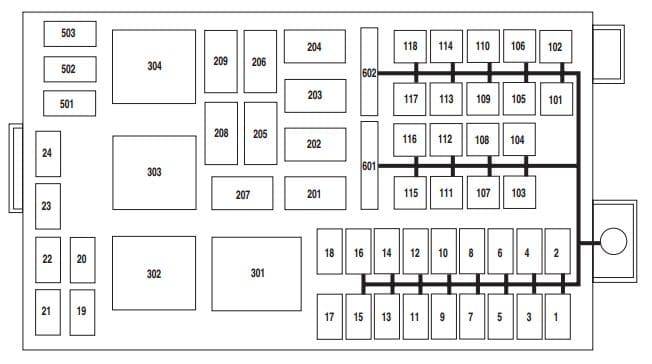
Power distribution box
The power distribution box is located in the engine compartment.
| Fuse/relay | Ampere rating [A] | Description |
| 1 | 25* | Ignition switch (Key in, RUN 1, RUN 2), Hazards |
| 2 | 25* | Ignition switch (RUN/START, RUN/ACC, START) |
| 3 | 10* | Powertrain Control Module (PCM) keep alive power |
| 4 | 20* | Fuel relay feed |
| 5 | 10* | Rear Air Suspension Module (RASM), VAPS |
| 6 | 15* | Alternator regulator |
| 7 | 30* | PCM relay feed |
| 8 | 20* | Driver’s Door Module (DDM) |
| 9 | 15* | Ignition coil relay feed |
| 10 | 20* | Horn relay feed |
| 11 | 15* | A/C clutch relay feed |
| 12 | 25* | Audio |
| 13 | 20* | Instrument panel power point |
| 14 | 20* | Stop lamp switch |
| 15 | 20* | Heated seats |
| 16 | 15* | Foglamps |
| 17 | — | Not used |
| 18 | — | Not used |
| 19 | 15* | Injectors |
| 20 | 15* | PCM, Mass Air Flow (MAF) sensor, IAT |
| 21 | 15* | Powertrain loads and sensors, A/C clutch relay coil |
| 22 | — | Not used |
| 23 | — | Not used |
| 24 | — | Not used |
| 101 | 40** | Blower relay feed |
| 102 | 50** | Cooling fan |
| 103 | 50** | Instrument panel (I/P) fuse box feed #1 (I/P fuses 19, 21, 23, 25 and 27) |
| 104 | 40** | Instrument panel (I/P) fuse box feed #2 (I/P fuses 1, 3, 5, 7, 8 and 9) |
| 105 | 30** | Starter relay feed |
| 106 | 40** | Anti-lock Brake System (ABS) module (Pump) |
| 107 | 40** | Rear defroster relay feed |
| 108 | 20** | Moonroof |
| 109 | 20** | ABS module (Valves) |
| 110 | 30** | Wiper module |
| 111 | — | Not used |
| 112 | 30** | Air suspension compressor |
| 113 | — | Not used |
| 114 | — | Not used |
| 115 | — | Not used |
| 116 | — | Not used |
| 117 | — | Not used |
| 118 | — | Not used |
| 201 | 1⁄2 ISO relay | A/C clutch |
| 202 | — | Not used |
| 203 | 1⁄2 ISO relay | Ignition coil |
| 204 | 1⁄2 ISO relay | PCM |
| 205 | 1⁄2 ISO relay | Fog lamps |
| 206 | 1⁄2 ISO relay | Fuel |
| 207 | — | Not used |
| 208 | — | Not used |
| 209 | 1⁄2 ISO relay | Horn |
| 301 | Full ISO relay | Starter |
| 302 | Full ISO relay | Air compressor |
| 303 | Full ISO relay | Blower |
| 304 | Full ISO relay | Power windows relay (RUN/ACC) |
| 501 | Diode | A/C clutch |
| 502 | Diode | PCM |
| 503 | Diode | Horn, Door latch |
| 601 | 20A Circuit breaker | Power seats, Lumbar |
| 602 | 20A Circuit breaker | Power windows relay feed (RUN/ACC) |
| * Mini fuse ** Cartridge fuse | ||
WARNING: Terminal and harness assignments for individual connectors will vary depending on vehicle equipment level, model, and market.

