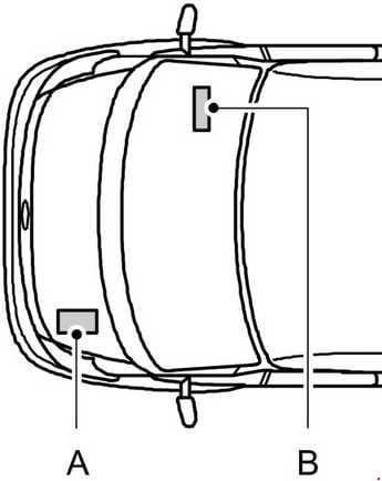
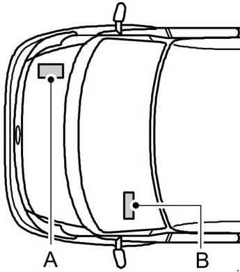
Location
Left-hand drive
Right-hand drive
A – Engine compartment fuse box
B – Passenger compartment fuse box
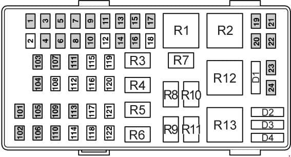
Engine compartment fuse box
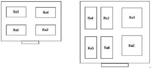
Additional Relay Box / Boxes Under Expansion Tank
| No. |
A |
Circuits protected |
| 1 | 5 | Auto shift manual transmission |
| 2 | – | Not used |
| 3 | 20 | Daytime running lamps, dipped beam |
| 4 | 5 | Battery voltage sensor (Diesel engines) |
| 5 | 20 | Fuel cut-off switch |
| 6 | 30 | Towing equipment |
| 7 | 15 | Horn |
| 8 | 20 | ABS |
| 9 | 20 | Main beam |
| 10 | 10 | Air conditioning |
| 11 | 20 | Windscreen washers, rear window washers |
| 12 | – | Not used |
| 13 | 30 | Multi-function lever, windscreen wipers |
| 14 | 15 | Reversing lamp |
| 15 | 5 | Engine immobilisation system module |
| 16 | 5 | Electronic engine control |
| 17 | 30 | Towing equipment |
| 18 | – | Not used |
| 19 | 5 | Auto shift manual transmission |
| 20 | 15 | Auto shift manual transmission |
| 21 | 20 | Engine management |
| 22 | 20 | Fuel pump |
| 23 | 10 | Dipped beam, right-hand side |
| 24 | 10 | Dipped beam, left-hand side |
| 101 | 40 | ABS |
| 102 | 40 | Heated windscreen left-hand side |
| 103 | 50 | Main power supply to electrical system |
| 104 | 50 | Main power supply to electrical system |
| 105 | 40 | Engine cooling fan (2.0 l Diesel and 2.3 l DOHC engines) |
| 106 | 30 | Ignition |
| 107 | 30 | Ignition |
| 108 | – | Not used |
| 109 | 40 | Engine cooling fan (2.0 l Diesel and 2.3 l DOHC engines) |
| 110 | 40 | Heated windscreen, right-hand side |
| 111 | 30 | Ignition |
| 112 | – | Not used |
| 113 | 40 | Auto shift manual transmission |
| 114 | – | Not used |
| 115 | – | Not used |
| 116 | – | Not used |
| 117 | – | Not used |
| 118 | – | Not used |
| 119 | – | Not used |
| 120 | – | Not used |
| 121 | – | Not used |
| 122 | – | Not used |
| Relay | ||
| R1 | Starter Motor | |
| R2 | Glow Plugs / Cooling Fan | |
| R3 | Horn | |
| R4 | Main Beam | |
| R5 | Generator Cut-Off | |
| R6 | Dipped Beam | |
| R7 | Engine Management (PCM) | |
| R8 | Bulb Check (Vehicles Without ABS) | |
| R9 | Fuel Pump (TDdi Engines), Injector Module (TDci Engines) | |
| R10 | Air Conditioning WOT (Wide Open Throttle) | |
| R11 | Lift Pump (Some TDdi Engines) | |
| R12 | Engine Cooling Fan | |
| R13 | Ignition | |
| Ra1 | Air Susspension Compressor | |
| Ra2 | Engine Cooling Fan High Speed | |
| Ra3 | Trailer Tow Indicators Left Hand | |
| Ra4 | Trailer Tow Indicators Right Hand | |
| Ra5 | Trailer Tow | |
| Ra6 | – | |
| Diodes |
||
| D1 | – | |
| D2 | – | |
| D3 | Trailer Tow RH Indicator / or Air Conditioning Clutch | |
| D4 | Trailer Tow LH Indicator / or Air Conditioning Indicator Ligh | |
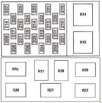
Passenger compartment fuse box
Alternative Relay Box
| o. |
A |
Circuits protected |
| 201 | 15 | Instrument cluster, rear window wiper, clock |
| 202 | 5 | Heated windscreen |
| 203 | 20 | Fog lamps |
| 204 | – | Not used |
| 205 | 15 | Light control, direction indicators, multi-function lever, engine management, ignition |
| 206 | 5 | Number plate light |
| 207 | 10 | Airbag module |
| 208 | 10 | Instrument cluster illumination |
| 209 | 15 | Side lamps |
| 210 | 15 | Tachometer, clock |
| 211 | 30 | Rear heater blower motor |
| 212 | 10 | Cigar lighter |
| 213 | 10 | Rear air conditioning |
| 214 | 15 | Interior lamps, electric mirrors |
| 215 | 20 | Heated windscreen, heated front seats, auxiliary heater |
| 216 | 20 | Auxiliary power socket |
| 217 | 15 | Heated rear window, heated exterior mirrors |
| 218 | – | Not used |
| 219 | 30 | Electric windows |
| 220 | 20 | Heated rear window |
| 221 | 15 | Brake lamp switch |
| 222 | 15 | Radio |
| 223 | 30 | Heater blower motor |
| 224 | 20 | Headlamp switch |
| 225 | 15 | Air conditioning |
| 226 | 20 | Hazard warning flashers, direction indicators |
| 227 | 5 | Radio, ABS |
| Relay | ||
| R14 | Windscreen Wiper | |
| R15 | Battery Saver / D+ (Only switches on with engine running) | |
| R16 | Heated Screen Right Hand Side | |
| R17 | Bus / Rear Door Buzzer Relay | |
| R18 | Interior Light | |
| R19 | Rear Door Warning Buzzer (buzzer unit itself not a relay) | |
| R20 | Heated Screen Left Hand Side (Timer relay) | |
| R21 | Rear Wiper | |
| R22 | Heated Rear Window / Heated Mirrors | |
1) Central Locking Fuses: 2 x 15A located under/taped too, steering column.
2) Heater Blower relay is behind centre console (where Fitted),
3) Auxiliary Heater relay is under drivers seat (where fitted).
4) Air Conditioning relay is screwed to rear of engine bay (where fitted), and on LPG models, all LPG control modules / relays arc located behind a removable panel on drivers side dash.
WARNING: Terminal and harness assignments for individual connectors will vary depending on vehicle equipment level, model, and market.
